
Home
About
MODBUS
fc01
fc02
fc03
fc04
fc05
fc06
fc15
fc16
ASCII
TCP
exceptions
About
Enron
MODBUS
RTU Master
RTU Slave
TCP Client
Download
Purchase
Contact
Frequently Asked Questions
How is data stored in Standard Modbus?
What are the formats of Modbus commands and responses?
What is byte and word ordering?
What is the difference between Modbus ASCII and Modbus RTU?
What are extended register addresses?
How does 2-byte addressing work?
How can you send events and historical data?
What is Modbus?
Modbus is a serial communication protocol developed by Modicon published by Modicon® in 1979 for use with its programmable logic controllers (PLCs). In simple terms, it is a method used for transmitting information over serial lines between electronic devices. The device requesting the information is called the Modbus Master and the devices supplying information are Modbus Slaves. In a standard Modbus network, there is one Master and up to 247 Slaves, each with a unique Slave Address from 1 to 247. The Master can also write information to the Slaves.
The official Modbus specification can be found at modbus.org/specs.php .
What is it used for?
Modbus is an open protocol, meaning that it's free for manufacturers to build into their equipment without having to pay royalties. It has become a standard communications protocol in industry, and is now the most commonly available means of connecting industrial electronic devices. It is used widely by many manufacturers throughout many industries. Modbus is typically used to transmit signals from instrumentation and control devices back to a main controller or data gathering system, for example a system that measures temperature and humidity and communicates the results to a computer. Modbus is often used to connect a supervisory computer with a remote terminal unit (RTU) in supervisory control and data acquisition (SCADA) systems. Versions of the Modbus protocol exist for serial lines (Modbus RTU and Modbus ASCII) and for Ethernet (Modbus TCP).
How does it work?
Modbus is transmitted over serial lines between devices. The simplest setup would be a single serial cable connecting the serial ports on two devices, a Master and a Slave.
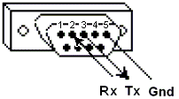
 >
>
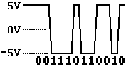
The data is sent as series of ones and zeroes called bits. Each bit is sent as a voltage. Zeroes are sent as positive voltages and a ones as negative. The bits are sent very quickly. A typical transmission speed is 9600 baud (bits per second).
What is hexadecimal?
When troubleshooting problems, it can be helpful to see the actual raw data being transmitted. Long strings of ones and zeroes are difficult to read, so the bits are combined and shown in hexadecimal. Each block of 4 bits is represented by one of the sixteen characters from 0 to F.
| 0000 = 0 | 0100 = 4 | 1000 = 8 | 1100 = C |
| 0001 = 1 | 0101 = 5 | 1001 = 9 | 1101 = D |
| 0010 = 2 | 0110 = 6 | 1010 = A | 1110 = E |
| 0011 = 3 | 0111 = 7 | 1011 = B | 1111 = F |
Each block of 8 bits (called a byte) is represented by one of the 256 character pairs from 00 to FF.
What is ASCII?
ASCII stand for American Standard Code for Information Interchange. In the same way that every 4 bits can be combined and represented by one of sixteen hexadecimal characters from 0 to F, every 8 bits (every byte) can be combined and represented by one of 256 ASCII characters, including the common keyboard characters. For example, some of the values for ASCII characters are...
| decimal (base10) |
binary (base2) |
Hex (base16) |
ASCII (base256) |
| 0 | 0000 0000 | 00 | null |
| 1 | 0000 0001 | 01 | " |
| 34 | 0010 0010 | 22 | # |
| 35 | 0010 0011 | 23 | $ |
| 36 | 0010 0100 | 24 | % |
| 47 | 0010 1111 | 2F | / |
| 48 | 0011 0000 | 30 | 0 |
| 49 | 0011 0001 | 31 | 1 |
| 56 | 0011 1000 | 38 | 8 |
| 57 | 0011 1001 | 39 | 9 |
| 58 | 0011 1010 | 3A | : |
| 64 | 0100 0000 | 40 | @ |
| 65 | 0100 0001 | 41 | A |
| 66 | 0100 0010 | 42 | B |
| 89 | 0101 1001 | 59 | Y |
| 90 | 0101 1010 | 5A | Z |
| 91 | 0101 1011 | 5B | [ |
| 95 | 0101 1111 | 5F | _ |
| 96 | 0110 0000 | 60 | ` |
| 97 | 0110 0001 | 61 | a |
| 122 | 0111 1010 | 7A | z |
| 123 | 0111 1011 | 7B | { |
| 174 | 1010 1110 | AE | ® |
| 255 | 1111 1111 | FF |
How is data stored in Standard Modbus?
Information is stored in the Slave device in four different tables.
Two tables store on/off discrete values (coils) and two store numerical values (registers).
The coils and registers each have a read-only table and read-write table.
Each table has 9999 values.
Each coil or contact is 1 bit and assigned a data address between
0000 and
270E.
Each register is 1 word = 16 bits = 2 bytes and also has data address between
0000 and
270E.
Coil/Register Numbers |
Data Addresses |
Type | Table Name |
1-9999 |
0000 to 270E |
Read-Write | Discrete Output Coils |
10001-19999 |
0000 to 270E |
Read-Only | Discrete Input Contacts |
30001-39999 |
0000 to 270E | Read-Only | Analog Input Registers |
40001-49999 |
0000 to 270E | Read-Write | Analog Output Holding Registers |
Coil/Register Numbers can be thought of as location names since they do not appear in the actual messages. The Data Addresses are used in the messages.
For example, the first Holding Register, number 40001, has the Data Address
0000.
The difference between these two values is the offset.
Each table has a different offset. 1, 10001, 30001 and 40001.
What is the Slave ID?
Each slave in a network is assigned a unique unit address from 1 to 247. When the master requests data, the first byte it sends is the Slave address. This way each slave knows after the first byte whether or not to ignore the message.
What is a function code?
The second byte sent by the Master is the Function code. This number tells the slave which table to access and whether to read from or write to the table.
| Function Code | Action | Table Name |
| 01 (01 hex) | Read | Discrete Output Coils |
| 05 (05 hex) | Write single | Discrete Output Coil |
| 15 (0F hex) | Write multiple | Discrete Output Coils |
| 02 (02 hex) | Read | Discrete Input Contacts |
| 04 (04 hex) | Read | Analog Input Registers |
| 03 (03 hex) | Read | Analog Output Holding Registers |
| 06 (06 hex) | Write single | Analog Output Holding Register |
| 16 (10 hex) | Write multiple | Analog Output Holding Registers |
What is a CRC?
CRC stands for Cyclic Redundancy check. It is two bytes added to the end of every modbus message for error detection. Every byte in the message is used to calculate the CRC. The receiving device also calculates the CRC and compares it to the CRC from the sending device. If even one bit in the message is received incorrectly, the CRCs will be different and an error will result.
Here is a spreadsheet CRC calculator for messages up to 16 bytes.
To download a copy, right click and select Save Target As...
What are the formats of Modbus commands and responses?
Follow the links in this table to see examples of the requests and responses.
| Data Addresses | Read | Write Single | Write Multiple |
| Discrete Output Coils 0xxxx | FC01 | FC05 | FC15 |
| Discrete Input Contacts 1xxxx | FC02 | NA | NA |
| Analog Input Registers 3xxxx | FC04 | NA | NA |
| Analog Output Holding Registers 4xxxx | FC03 | FC06 | FC16 |
FC = Function Code
What are data types?
The example for FC03 shows that register 40108 contains
AE41
which converts to the 16 bits
1010 1110 0100 0001
Great! But what does it mean? Well, it could mean a few things.
Register 40108 could be defined as any of these 16-bit data types:
A 16-bit unsigned integer (a whole number between 0 and 65535)
register 40108 contains AE41 = 44,609
(hex to decimal conversion)
A 16-bit signed integer (a whole number between -32768 and 32767)
AE41 = -20,927
(hex to decimal conversion that wraps, if its over 32767 then subtract 65536)
A two character ASCII string (2 typed letters)
AE41 = ® A
A discrete on/off value
(this works the same as 16-bit integers with a value of 0 or 1.
The hex data would be 0000
or 0001)
Register 40108 could also be combined with 40109 to form any of these 32-bit data types:
A 32-bit unsigned integer (a number between 0 and 4,294,967,295)
40108,40109 =
AE41 5652 = 2,923,517,522
A 32-bit signed integer (a number between -2,147,483,648 and 2,147,483,647)
AE41 5652 = -1,371,449,774
A 32-bit single precision IEEE floating point number.
This is a mathematical formula that allows any real number (a number with decimal
points) to represented by 32 bits with an accuracy of about seven digits.
AE41 5652 = -4.395978 E-11
Here is a spreadsheet
IEEE float calculator for inputs of 4 bytes or 2 words.
To download a copy, right click and select Save Target As...
A four character ASCII string (4 typed letters)
AE41 5652 = ® A V R
More registers can be combined to form longer ASCII strings. Each register being used to store two ASCII characters (two bytes).
What is byte and word ordering?
The Modbus specification doesn't define exactly how the data is
stored in the registers. Therefore, some manufacturers implemented
modbus in their equipment to store and transmit the higher byte first
followed by the lower byte. (AE
before 41).
Alternatively, others store and transmit the lower byte first (41
before AE).
Similarly, when registers are combined to represent 32-bit data types, Some devices store the higher 16 bits (high word) in the first register and the remaining low word in the second (AE41 before 5652) while others do the opposite (5652 before AE41)
It doesn't matter which order the bytes or words are sent in, as long as the receiving device knows which way to expect it.
For example, if the number 2,923,517,522 was to be sent as a 32 bit unsigned integer, it could be arranged any of these four ways.
also know as
AE41 5652
high byte first high word first
"big endian"
5652 AE41
high byte first low word first
41AE 5256
low byte first high word first
5256 41AE
low byte first low word first
"little endian"
What is a Modbus Map?
A modbus map is simply a list for a slave device that defines
- what the data is (eg. pressure or temperature readings)
- where the data is stored (which tables and data addresses)
- how the data is stored (data types, byte and word ordering)
Some devices are built with a fixed map that is defined by the manufacturer. While other devices allow the operator to configure or program a custom map to fit their needs.
What is the difference between Modbus ASCII and Modbus RTU?
The difference between these two modes is explained here.
What are extended register addresses?
Since the range of the analog output holding registers is 40001 to 49999, it implies that there cannot be more than 9999 registers. Although this is usually enough for most applications, there are cases where more registers would be beneficial.
Registers 40001 to 49999 correspond to data addresses 0000 to 270E. If we utilize the remaining data addresses 270F to FFFF, over six times as many registers can be available, 65536 in total. This would correspond to register numbers from 40001 to 105536.
Many modbus software drivers (for Master PCs) were written with the 40001 to 49999 limits and cannot access extended registers in slave devices. And many slave devices do not support maps using the extended registers. But on the other hand, some slave devices do support these registers and some Master software can access it, especially if custom software is written.
How does 2-byte slave addressing work?
Since a single byte is normally used to define the slave address and each slave on a network requires a unique address, the number of slaves on a network is limited to 256. The limit defined in the modbus specification is even lower at 247.
To get beyond this limit, a modification can be made to the protocol to use two bytes for the address. The master and the slaves would all be required to support this modification. Two byte addressing extends the limit on the number of slaves in a network to 65535.
By default, the Simply Modbus software uses 1 byte addressing. When an address greater than 255 is entered, the software automatically switches to 2 byte addressing and stays in this mode for all addresses until the 2 byte addressing is manually turned off.
How can you send events and historical data?
Enron Modbus includes commands for moving events and historical data..
What is Enron Modbus?
Enron Modbus is a modification to the standard Modicon modbus communication protocol developed by Enron Corporation.
See Enron Modbus for details.
What else?
If you read this page, We would love to hear your comments. Please send an email to info@simplymodbus.ca and let us know what you found helpful and what topics we could add, expand or clarify.
Home • FAQ • Enron • Download • Purchase • Contact
Copyright © 2024 Simply Modbus. All rights reserved