
Home
About
MODBUS
About
Enron
MODBUS
RTU Master
RTU Slave
TCP Client
manual1
manual7
manual8
Download
Purchase
Contact
Operation Manual
Simply Modbus TCP Client 1.4
Modbus TCP Client Software
System Requirements:
Windows NT, 95, 2000, XP. (not recommended for Windows 7 or Vista )
display resolution: 800 x 600 minimum
Installation - Simply Modbus TCP Client 1.4 (1.65 MB) :
Click to download SimplyModbusTCPclient1.4.zip
Unzip the compressed files into a common folder on your hard drive.
Simply Modbus TCP Client 1.4.exe - the program
Read me TCP Client 1.4.txt
- documentation
Read me for Windows7.txt - documentation
Known Issues with version 1.4: Two instances normally appears in the taskbar while the program is running, the runtime engine and the program itself, Sometimes the runtime engine does not quit when the program is closed, although it is not consistent and behaves differently on different PCs. It is more likely to happen when the program is opened and closed within a few seconds. Waiting longer or sending a request before closing may help it quit properly. It may quit by itself after a few minutes on some Windows 7 and systems. Although it's okay on others.
Work Arounds: It can be forced to quit by right clicking on the taskbar item and selecting close. Using Alt-F4 to quit the program also works better in some cases.
Simply Modbus TCP Client 7.1.2 looks and runs exactly like Simply Modbus TCP Client 1.4 but was created using a newer compiler. It is a significantly larger download and has an install program. It appears to be more stable with the newer Windows versions. see.....manual7
Simply Modbus TCP Client 7.1.2 will automatically use a license for Simply Modbus TCP Client if already installed on the PC.
Starting the program
Double-click on Simply Modbus TCP Client 1.4.exe.
You will see the demonstration startup window.
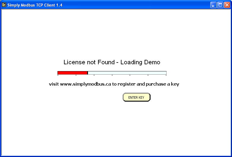
The progress bar will take approximately 15 seconds to load the demonstration version.
During this time, you can press the ENTER KEY and see
After purchasing and receiving a license key by email, enter the key and press OK.
The licensed program
- goes immediately to the main Simply Modbus Read window and bypasses the
Loading Demo startup window.
- allows unlimited reads and writes.
The demo version
- offers full functionality
- requires a program restart to send more than six read requests or two write commands.
The Simply Modbus TCP Client Read Window

Controls (inputs) that can be changed by the user are shown in yellow.
Indicators (outputs) shown in blue cannot be changed.
Set the controls to build the Request string.
![]() Select TCP or RTU-over-TCP mode. more info...
Select TCP or RTU-over-TCP mode. more info...
![]() Select the IP Address of the Server (Slave device) that you wish to connect to.
Select the IP Address of the Server (Slave device) that you wish to connect to.
![]() Select the Server's Port to connect to.
Select the Server's Port to connect to.
![]() Press the Connect button and the program will attempt to connect to the Modbus Server.
Press the Connect button and the program will attempt to connect to the Modbus Server.
Each 6 second attempt will count up on the button after the word CONNECTING.
The program will keep trying to connect until a connection is made or the button is pressed again.
![]() The connection status is displayed as CONNECTED or NOT CONNECTED.
The connection status is displayed as CONNECTED or NOT CONNECTED.

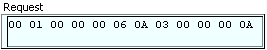
When in RTU-over-TCP Mode, the first six bytes of the MBAP header are not present. The Request starts with the Slave ID.
 The 7th byte in the Request string in TCP Mode (The 1st byte in RTU-over-TCP mode)
The unit address of the Server (Slave) device to get data from. normal range: 1 to 247
more info...
The 7th byte in the Request string in TCP Mode (The 1st byte in RTU-over-TCP mode)
The unit address of the Server (Slave) device to get data from. normal range: 1 to 247
more info...
 Setting a Slave ID over 255 will automatically check this box and allow Slave IDs up to 65535.
more info...
Setting a Slave ID over 255 will automatically check this box and allow Slave IDs up to 65535.
more info...
Remains on for all addresses until the Slave ID is lowered below 256 and the box manually unchecked.
 The 8th byte in the Request string in TCP Mode (The 7th byte in RTU-over-TCP mode
Can be automatically set
more info...
Used to select which table to read from.
more info...
Read Window supports Function codes 01, 02, 03 & 04
 The 9th & 10th bytes in the Request string in TCP Mode (The 3rd & 4th bytes in RTU-over-TCP mode)
The coil or register number at the start of the block to read.
more info...
 This value is subtracted from the First Register to give the data address used in the Request.
 The 11th & 12th bytes in the Request string. in TCP Mode (The 5th & 6th bytes in RTU-over-TCP mode)
The quantity of registers or coils in the block to read.
 check to automatically set the default values function code, offset and register size
when the value of First Register is changed.
 The size of the registers in the block to be read.
This value should be set to 16 bit registers to read standard modbus registers.
and set to 1 bit coils to read standard modbus coils.
32 bit registers should be used for Enron modbus only.
more info...
Events: This box is checked when reading Enron events from register 32 more info...
History: This box is checked when reading Enron historical records from register 701-799 more info...

TCP Mode
RTU-over-TCP Mode
crc In RTU-over-TCP Mode, the last 2 bytes of the Request are the cyclic redundancy check.
These are error detection bytes.
They are not present in TCP Mode
more info...
Auto Set values:
| First Register | function code | minus offset | register size |
| 1 to 10000 | 1 | 1 | 1 bit coils |
| 10001 to 10000 | 2 | 10001 | 1 bit coils |
| 30001 to 40000 | 4 | 30001 | 16 bit registers |
| 40001 & greater | 3 | 40001 | 16 bit registers |
Exceptions (for reading Enron modbus data):
| First Register | function code | minus offset | register size |
| 32 (events) | 3 | 0 | 32 bit registers |
| 701 to 799 (history) | 3 | 0 | 32 bit registers |
| 1001 to 1999 | 1 | 0 | 1 bit coils |
| 3001 to 3999 | 3 | 0 | 16 bit registers |
| 5001 to 5999 | 3 | 0 | 32 bit registers |
| 7001 to 7999 | 3 | 0 | 32 bit registers |
Physical Connection
Before sending a message, the ethernet port needs to be physically connected to a network with Modbus servers.
Sending the Request
Press the SEND button. The program then monitors for incoming data and displays all bytes received in the Response indicator. The SEND button is greyed out until a connection is established with the Modbus Server (Slave device).
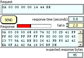
While receiving, the response time counts up with a progress bar.
Receiving stops when the expected response bytes are received or the time reaches the fail in value entered.
The 'expected response bytes' indicator is calculated from the input settings.
The response timer stops when this many bytes are received.
Troubleshooting
Check the IP Address and Port in the Modbus Server (Slave device) to make sure it matches the settings in the TCP Client program (Master device)
Reading the Response
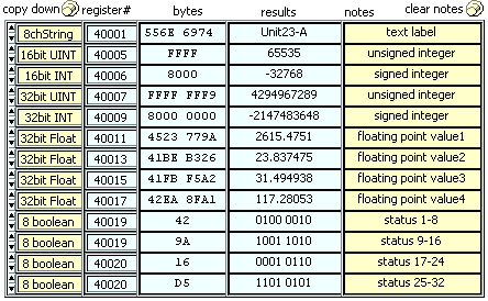
The data bytes in the response are displayed in the bytes column of the response table.
Use the pull-down boxes in the first column to set the data type for each value.
more info...
The copy down button sets all data types to match the setting for the first value.
 The bytes and words can be swapped by toggling the High/Low check boxes.
The bytes are re-processed immediately as the settings are changed and the results are shown in the fourth column.
Sending another request for a new response is not required for a recalculation.
A notes column is provided to enter labels for the values.
 Press the clear notes button to blank the whole notes column.
Byte History Log
All bytes sent and received are added to the byte history log with date/time stamps.
 Displays a 'Save As..' dialog box to allow the log contents to be saved to a text file.
 Empties the log contents.
Log Results
All data results received can be saved to a data log with date/time stamps.
![]() Displays a 'Save As..' dialog box to create a tabbed-text data file for
logging the results.
Displays a 'Save As..' dialog box to create a tabbed-text data file for
logging the results.
register# and notes are used as column headers in the file.
When data is received, a row is added to the file with date/time and the results.
Pressing the button again will close the file and stop logging the results.
The data file can be loaded into just about any system or progam like
Excel.
Send Continuously
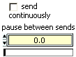
Check this box to send back to back requests.
The seconds after the start of one send request until the start of the next send request.
Statistics

The seconds taken for the slave to respond to last message.
The number of message responses received (meeting the expected response
bytes).
The number of message with an incomplete or absent response
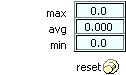
The longest amount of seconds taken for a response (not including failed responses).
The average amount of seconds taken for a response (not including failed responses).
The shortest amount of seconds taken for a response (not including failed responses).
Sets all statistical values back to zero.
Save and Restore Configurations
 Displays a 'Save As..' dialog box to allow saving the current settings and
results to a text file.
Displays a 'Save As..' dialog box to allow saving the current settings and
results to a text file.

Displays a 'Open File' dialog box to allow selecting a previously saved settings file to load.
The configuration file is saved in tabbed text format (tab separated values) and appears like this in notepad.
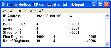
The preset tabs in Notepad cause the cells with long
labels to push the other columns over.
Sending it to, or opening it
from, a spreadsheet program like Excel will use the tabs as column delimiters
as shown here...
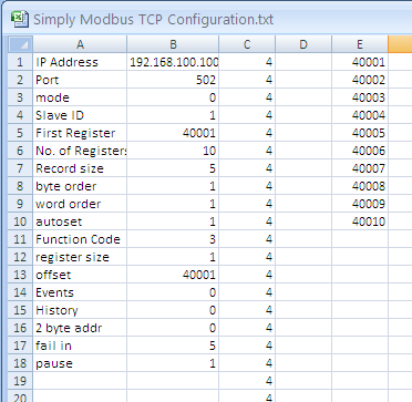
1st column contains descriptions, 2nd column contains values
3rd column contains the data types 0 through 11 in the order shown in its pull down menu.
4th column is empty, 5th column contains the register numbers.
6th column contains the register values from the last poll, if any
------------------------------------------------------------------------------------
Writing Data
![]() Displays the Simply Modbus TCP Client Write1.4 window
Displays the Simply Modbus TCP Client Write1.4 window
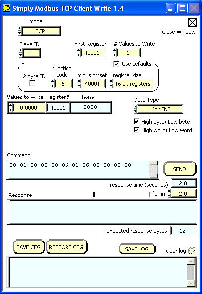
Controls (inputs) that can be changed by the user are shown in yellow.
Indicators (outputs) shown in blue cannot be changed.
Set the controls to build the Command string.
The mode setting is copied from the previous window and can also be changed here.
![]() Select TCP or RTU-over-TCP mode. more info...
Select TCP or RTU-over-TCP mode. more info...
The IP Address and Port are copied from the previous window and cannot be changed here.
The 7th byte in the Command string. in TCP Mode (The 1st byte in RTU-over-TCP mode)
The unit address of the Slave device to get data from. normal range: 1 to 247
more info...
Setting a Slave ID over 255 will automatically check this box and allow Slave IDs up to 65535.
more info...
Remains on for all addresses until the Slave ID is lowered below 256 and the box manually unchecked.
The 8th byte in the Command string. in TCP Mode (The 7th byte in RTU-over-TCP mode)
Can be automatically set more info...
Used to select which table to write to.
more info...
Write Window supports Function codes 05, 06, 15 & 16
The 9th & 10th bytes in the Command string. in TCP Mode (The 3rd & 4th bytes in RTU-over-TCP mode)
The coil or register number at the start of the block to be written.
more info...
This value is subtracted from the First Register to give the data address used in the Command.
![]() The 11th & 12th bytes in the Command string. in TCP Mode (The 5th & 6th bytes in RTU-over-TCP mode)
The 11th & 12th bytes in the Command string. in TCP Mode (The 5th & 6th bytes in RTU-over-TCP mode)
The quantity of registers or coils in the block to be written.
Check to automatically set the default values for function code, offset and register size
when the value of First Register is changed.
The size of the registers in the block to be written.
This value should be set to 16 bit registers to write standard modbus registers.
and set to 1 bit coils to write standard modbus coils.
32 bit registers should be used for Enron modbus only.
more info...
Auto Set values:
| First Register | function code | minus offset | register size |
| 1 to 7000 | 5 | 1 | 1 bit coils |
| 7001 to 7999 (Enron modbus) | 16 | 0 | 32 bit registers |
| 8000 to 10000 | 5 | 1 | 1 bit coils |
| 10001 to 30000 | 5 | 10001 | 1 bit coils |
| 30001 to 40000 | 6 | 30001 | 16 bit registers |
| 40001 & greater | 6 | 40001 | 16 bit registers |
Data to Write
![]()
The values to write are entered in the table shown. The table size is automatically adjusted as the #values to write is changed.
![]() Use this pull-down box to set the data type for the whole table to be written.
Use this pull-down box to set the data type for the whole table to be written.
The bytes and words can be swapped by toggling the High/Low check boxes.
Sending the Command
Press the SEND button. The program then monitors for incoming data and displays all bytes received in the Response indicator.

While receiving, the response time counts up with a progress bar.
Receiving stops when the expected response bytes are received or the time reaches the fail in value entered.
The 'expected response bytes' indicator is calculated from the input settings.
The response timer stops when this many bytes are received.
Reading the Response
The data bytes in the response are displayed in the bytes column of the response table.
Byte History Log
All bytes sent and received are added to the byte history log with date/time stamps.
Displays a 'Save As..' dialog box to allow saving the log contents to a text file.
Empties the log contents
Save and Restore Configurations
Displays a 'Save As..' dialog box to allow saving the current settings to a text file.
Displays an 'Open File' dialog box to allow selecting a previously saved settings file to load.
Press the Close box in the top corner to Exit the Write program.
Home • FAQ • Enron • Download • Purchase • Contact
Copyright © 2020 Simply Modbus. All rights reserved