
Home
About
MODBUS
About
Enron
MODBUS
RTU Master
RTU Slave
manual2
manual7
manual8
TCP Client
Download
Purchase
Contact
Operation Manual
Simply Modbus Slave 2.1
Modbus RTU Slave and Modbus ASCII Slave Software
System Requirements:
Windows NT, 95, 2000, XP. (not recommended for Windows 7 or Vista )
display resolution: 800 x 600 minimum
PC with serial port (built in, serial card or USB serial port)
Installation - Simply Modbus Slave 2.1 (1.75 MB) :
Click to download SimplyModbusSlave2.1.zip
Unzip the compressed files into a common folder on your hard drive.
Simply Modbus Slave 2.1.exe - the program
serpdrv
- serial port driver
Read me Slave 2.1.txt
- documentation
Read me for Windows7.txt - documentation
Known Issues with version 2.1: Two instances normally appears in the taskbar while the program is running, the runtime engine and the program iself, Sometimes the runtime engine does not quit when the program is closed, although it is not consistent and behaves differently on different PCs. It is more likely to happen when the program is opened and closed within a few seconds. Waiting longer or sending a request before closing may help it quit properly. It may quit by itself after a few minutes on some Windows 7 and Vista systems. Although it's okay on others.
Work Arounds: It can be forced to quit by right clicking on the taskbar item and selecting close. Using Alt-F4 to quit the program also works better in some cases.
Simply Modbus Slave 7.1 looks and runs exactly like Simply Modbus Slave 2.1 but was created using a newer compiler. It is a significantly larger download and has an install program. It appears to be more stable with the newer Windows versions. see.....manual7
Simply Modbus Slave 7.1 will automatically use a license for Simply Modbus Slave if already installed on the PC.
Starting the program
Double-click on Simply Modbus Slave 2.1.exe.
You will see the demonstration startup window.
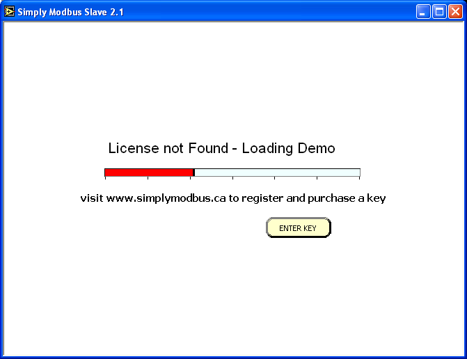
The progress bar will take approximately 15 seconds to load the demonstration version.
During this time, you can press the ENTER KEY and see
After purchasing and receiving a license key by email, enter the key and press OK.
The licensed program
- goes immediately to the main Simply Modbus Read window and bypasses the demonstration startup window.
- allows unlimited reads and writes.
The demo version
- offers full functionality
- requires a program restart to send more than six replies to requests.
The Simply Modbus Slave Window
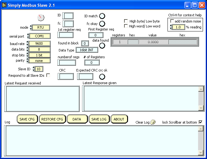
Program Summary:
When the program is opened, the circular clock indicator spins to show that the program is running. The program monitors the chosen serial port looking for incoming bytes from a modbus master. All bytes received (and sent) are displayed in the 'Log'.
The most recent request received is displayed in the indicator labelled "Latest Request received". A lookup is done to determine if the request has a valid SlaveID, function code, data addresses, valid data if writing and valid error detection bytes (CRC or LRC.
The request must meet the following 2 conditions before a response is generated and sent:
1) The ID in the request (the first byte received) must match the entered Slave ID,
or 'Respond to all Slave IDs' must be checked.
If the ID does not match, the Slave program will ignore the request since it is intended for a different slave.
2) The CRC (if RTU mode) or LRC (if ASCII mode) at the end of the request must be correct.
The request must meet the following additional conditions before a
response with data is generated and sent:
3) the
request must have a function code that matches enabled data in the
tables.
Function code 03 or 04 to read registers with a block of register data
set with the same code.
Function code 06 or 16 to write registers with a block of register data
set as read/write.
Function code 01 or 02 to read coils with a block of coil data set with
the same code.
Function code 05 or 15 to write coils with a block of coil data set as
read/write.
If not, an exception code 01 is generated and sent.
4) The requested registers or coils must exist in an enabled block. More
specifically, the request must be for register
or coil addresses with a hex values that match the register number minus
offset for one of the enabled tables.
If not, an exception code 02 is generated and sent.
For example, A request for 0003 addresses starting from 0002 will match
a block setup with Registers 40001 to
40008 and offset 40001. It will reply with data from 40003, 40004 &
40005. A request for 0007 addresses
starting from 0002 will not match the same block, since it needs
registers 40003 through 40009.
Since 40009 does not exist in the block, an exception code 02 would be
generated and sent.
5) When receiving function codes that request writing data, the data
size and format must be correct.
If not, an exception code 03 is generated and sent.
For example, A FC16 request to write 0005 16bit addresses must contain
10 data bytes (two per address),
otherwise an exception code 03 would be generated and sent.
When a response is generated, it is written to the serial port and the
Log.
On a multi-dropped network (eg. RS485) with multiple slaves, this application will also receive responses from other slaves.
All messages received will be monitored and processed to determine if they are valid requests from a modbus master.
Setup Details:
Controls (inputs) that can be changed by the user are shown in yellow.
Indicators (outputs) that cannot be changed are shown in blue.
Enter the input information in the controls to match the Slave you wish to emulate.
 Select RTU or ASCII mode. more info...
Select the serial port on your PC that is connected to a modbus master.
Range = COM1 to COM10
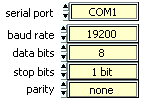
serial settings: Set these settings to match the setting of the modbus slave device connected.
baud: The baud rate (bits per second) of the serial connection.
data bits: The number of data bits in each byte, RTU mode requires 8, ASCII mode is usually 7 but may be 8.
stop bits: The number of stop bits for each byte sent. allowable values are 1, 1.5 or 2 .
parity: The value of the parity bit for each byte sent. allowable values are none, odd, even, mark or space.

The 1st byte in the Request and Response strings
The unit address of the Slave device to be emulated. normal range: 1 to 247
The program will only respond to requests directed to this Slave ID.
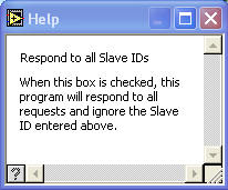
 When this box is checked, the program will respond to requests directed to any Slave ID.
Other Settings:

When checked, the program will send the data high byte first
When checked, the program will send the data high word first for 32 bit data types.

When checked, the program will apply a
random multiplier to the values found in the tables
to a maximum of the '%reading' value entered.
The program will then give slightly different responses when the same
request is repeated.
![]()
Context help is available by pressing
Ctrl-H while in the program.
Information is displayed about items as the cursor hovers over them.
For example...
Byte History Log
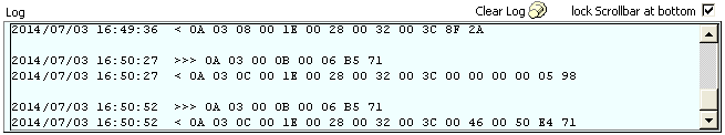
All bytes sent and received are added to the byte history log with date/time stamps.
 Displays a 'Save As..' dialog box to allow the log contents to be saved to a text file.
 Empties the log contents.
![]() Uncheck this box to keep the log from scrolling when new data is added.
Uncheck this box to keep the log from scrolling when new data is added.
![]() Displays information about the program including the program version.
Displays information about the program including the program version.
Press the Close box 'X' in the top corner to Exit the program.
Data Table Setup Details:
Press the
![]() button to display and change the register and coil
tables.
button to display and change the register and coil
tables.
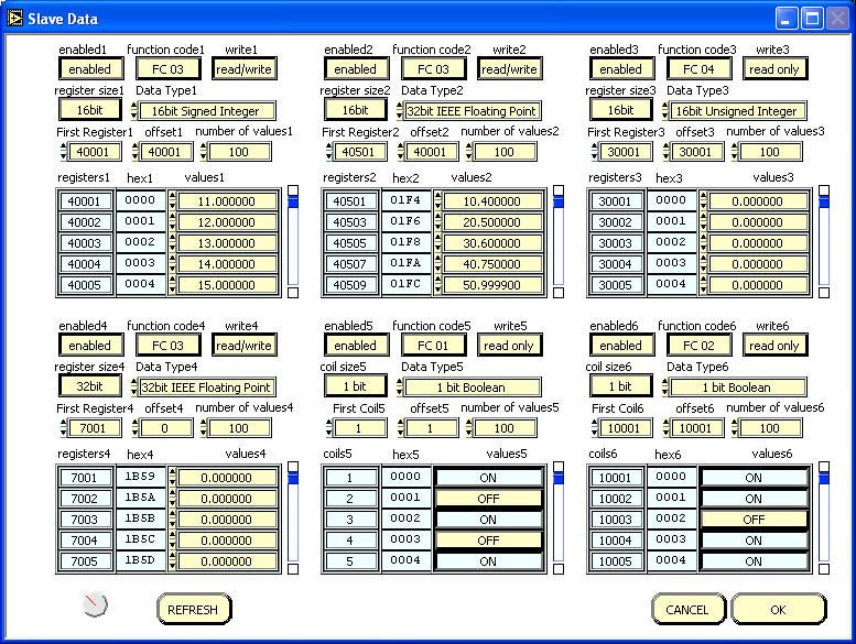
Six data tables can be setup that contain the blocks of data for the slave to respond with.
Blocks 1 to 4 are registers for storing numerical data
Blocks 5 to 6 are coils for storing boolean (on/off) data
![]() Each block can be set to enabled or disabled.
Each block can be set to enabled or disabled.
![]() Each register block is set to respond to either FC03 or FC04 read register requests.
Each register block is set to respond to either FC03 or FC04 read register requests.
Each coil block is set to respond to either FC01 or FC02 read coil requests.
![]() Each block can be set as read only to accept the only the function code above,
Each block can be set as read only to accept the only the function code above,
or read/write to allow the host to change the data with FC06&16 (for
registers) and FC05&15 (for coils)
![]() Each register block can be set as 16bit registers (typical for standard modbus),
Each register block can be set as 16bit registers (typical for standard modbus),
or 32bit registers (used for Enron modbus 32bit Int (5000) block or 32bit float (7000) block)
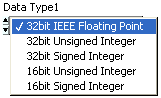
This control selects the data type for the table. more info...
All values in one table have the same data type.
Selectable as 32bit IEEE Floating Point
32bit Unsigned Integer (0 to 4.3 billion)
32bit Signed Integer (-2.1 to 2.1 billion)
16bit Unsigned Integer (0 to 65535)
16bit Signed Integer (-32768 to 32767)
Selecting a 32bit Data type with 16 bit register size will use 2 registers for each value.
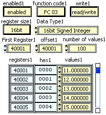
![]() Sets the register or coil numbers for the block.
Sets the register or coil numbers for the block.
![]() Sets the difference between the register number and the hex number used in the commands for each block.
Sets the difference between the register number and the hex number used in the commands for each block.
For example register#40005 minus offset 40001 = hex address 0004)
![]() This sets how many registers or coils are in each block.
This sets how many registers or coils are in each block.
 A read-only indicator displaying the register or coil numbers as set above.
![]() A read-only indicator displaying the hexadecimal equivalent of register or coil numbers minus the offset.
A read-only indicator displaying the hexadecimal equivalent of register or coil numbers minus the offset.
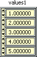
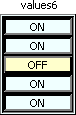 This is where the data values are entered.
![]() Press OK to accept the changes entered.
Press OK to accept the changes entered.
![]() Press CANCEL to leave the data unchanged.
Press CANCEL to leave the data unchanged.
Save and Restore Configurations
 Displays a 'Save As..' dialog box to allow saving the current settings to a text file.
The data file is saved in csv format (comma separated values).
The file can be edited with a spreadsheet application and reloaded into the program using RESTORE CFG
 Displays a 'Open File' dialog box to allow selecting a previously saved settings file to load.
The configuration file is saved in tabbed text format (tab separated values) and appears like this in notepad...
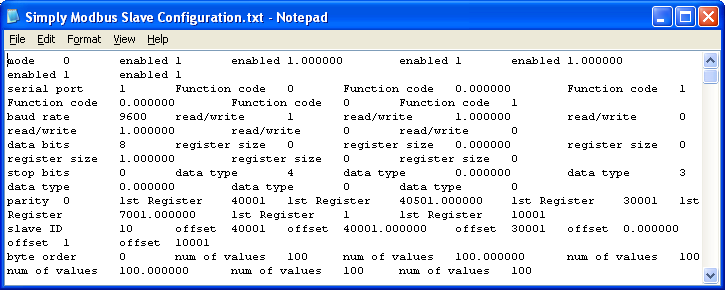
The preset tabs in Notepad cause the cells with long
labels to push the other columns over.
Sending it to, or opening it
from, a spreadsheet program like Excel will use the tabs as column delimiters
as shown here...
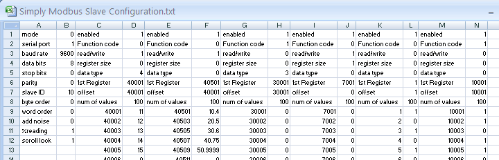
1st column contains descriptions, 2nd column contains
values:
Mode 0 = ASCII, 1 = RTU
serial port 1 = COM1, 2 = COM2 etc
baud rate
data bits
stop bits 0 = 1bit, 1 = 1.5bits, 2 = 2bits
parity 0 = none , 1 = odd, 2 = even, 3 =
mark, 4 = space
slave ID
byte order 0 = low byte first, 1 = high
byte first
word order 0 = low word first, 1 = high
word first
add noise 0 = unchecked, 1 = checked
%reading Integer
scroll lock 0 = unchecked, 1 = checked (lock
scrollbar at bottom)
The remaining columns contains the data from the 6 data tables:
enabled 0 = disabled, 1 = enabled
function code 0 = FC 03, 1 = FC 04 (for the
4 register tables)
function code 0 = FC 01, 1 = FC 02 (for the
2 coil tables)
read/write 0 = read only, 1 = read/write
register size 0 = 16 bit, 1 = 32 bit (not
applicable to coil tables)
data type 0 = 32bit IEEE
Floating Point (0 = 1 bit for coil tables)
1 = 32bit Unsigned Integer (0 to 4.3 billion)
2 = 32bit Signed Integer (-2.1 to 2.1 billion)
3 = 16bit Unsigned Integer (0 to 65535)
4 = 16bit Signed Integer (-32768 to 32767)
1st Register : the register number of the first
register including the offset
Offset : The offset between the register numbers
and their hex values for the table
Number of values: The size of the table
The table settings are followed by the register or coil numbers and
their corresponding values.
The data can be saved and edited within a spreadsheet and then loaded into the program with the RESTORE CFG button.
Physical Connection:
To receive requests from a modbus master before sending a message, the serial port needs to be physically connected to a modbus master device. The simplest connection is RS232C on a single serial cable.
DTE masters (PC serial ports) have DB9 male connectors which transmits on pin3, receives pin2 and grounds on pin5. A DCE slave will have a DB9 Female connector which will allow the use of a straight through cable. A DTE slave will have a DB9 Male connector and will require the use of a null modem cable.
The RS232 specification states a maximum distance of 50 feet at 20kbaud. Slightly longer connections are possible at slower baud rates depending on cable quality and noise in the area.
Modems and radios are used to transmit longer distances. These are typically DCE devices so straight through cables can be used. Some MDS non-spread spectrum radios require RTS Delay to be used so a 4th conductor is needed on pin 4.
RS485 converters can be used to extend the distance up to 4000 feet at 100kbaud. This can be a 4 wire or 2 wire system, depending on the converter. This also allows multi-dropping up to 32 devices on one pair of wires.
Program Operation:
Once the correct input data is entered, the program operates by itself.

When bytes are read on the serial port, they are displayed here.
The bytes are then processed to see if a response should be generated.
![]()
The first byte of the request is shown in 'ID'. This is the Slave Address that the Master is requesting a response from.
This hex value is converted to decimal and compared to the 'Slave ID' entered.
If they match or if "Respond to all Slave IDs" is selected, the 'ID match' indicator will turn green as shown.
![]()
The second byte of the request is shown in 'fc'. This is the Function code indicating which table to read from.
This program support function codes 01,02,03,04,05,06,15 (0F hex) and 16 (10 hex).
If one of these function codes is found in the request, the 'fc okay' indicator will turn green as shown.
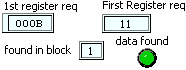
The 3rd and 4th bytes of the request are shown in '1st register req'. This is the register address of first register to read.
This number is converted from hex to decimal and shown in 'First Register
req'.
The program then looks for this register in the data tables showing the
function code above.
If found, the matching table is displayed in 'found in block', and the
'data found' indicator will turn green as shown.

The 5th and 6th bytes of the request are shown in 'number of regs'. This is the number of registers to read.
This hex value is converted to decimal and displayed in '# of Registers'.
![]()
The 7th and 8th bytes of the request are shown in 'CRC' (or 'LRC' if in ASCII mode).
The expected CRC (or LRC) is calculated from the first 6 bytes and
displayed in 'Expected CRC' (or 'Expected LRC').
If the two match, the 'crc ok' indicator will turn green as shown.
crc The last 2 bytes of a modbus RTU message are the cyclic redundancy check. These are error detection bytes more info...
lrc ASCII Mode messages are preceded with a colon and the crc is replaced with an lrc (longitudinal redundancy check), carriage return and line feed characters. more info...
If the 'ID match', 'fc okay', 'data found' and ' crc ok' indicators
all turn green, a response with data will be generated.
The data is read from the matching table and a response is generated and
returned.
A breakdown of the response is shown in the registers table
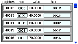
A breakdown of the response is shown in this table. A scrollbar
will appear for responses with more than 5 values as shown here.
The columns show the register number (including the offset), its value in hex,
the decimal value of the data and this value in hex.

The response string is generated from the data
and shown in 'Latest Response given'.
This is an example of a response with 6 data bytes.
The bytes in the above data response are explained here:
0A The Slave ID responding
03 The function code
06 The number of data bytes to follow
FF FF 00 00 00 01 The data bytes representing the values in the requested registers.
93 9E The CRC (or 'LRC' if in ASCII mode).
If the 'ID match' and ' crc ok' indicators both turn green, but the function code found is not supported, a response is generated with exception code '01'.
If the 'ID match' and ' crc ok' indicators both turn green, but the data is not found in the table, a response is generated with exception code '02'.
If the 'ID match' and ' crc ok' indicators both turn green, and a 'write data' function code 05, 06, 15, or 16 is found followed by valid data, the data is written to the tables and an appropriate response is generated.
If the 'ID match' and ' crc ok' indicators both turn green, and a 'write data' function code 05, 06, 15, or 16 is found followed by invalid or missing data, a response is generated with exception code '03'.
Troubleshooting
Check the physical connection to make sure the correct conductors are on the correct pins and the correct serial port.
Check the serial settings in the master device to make sure they match the settings in the slave.
Make sure the serial port driver file (serpdrv) is in the same folder as Simply Modbus Slave 2.1.exe
Home • FAQ • Enron • Download • Purchase • Contact
Copyright © 2020 Simply Modbus. All rights reserved